


Overview
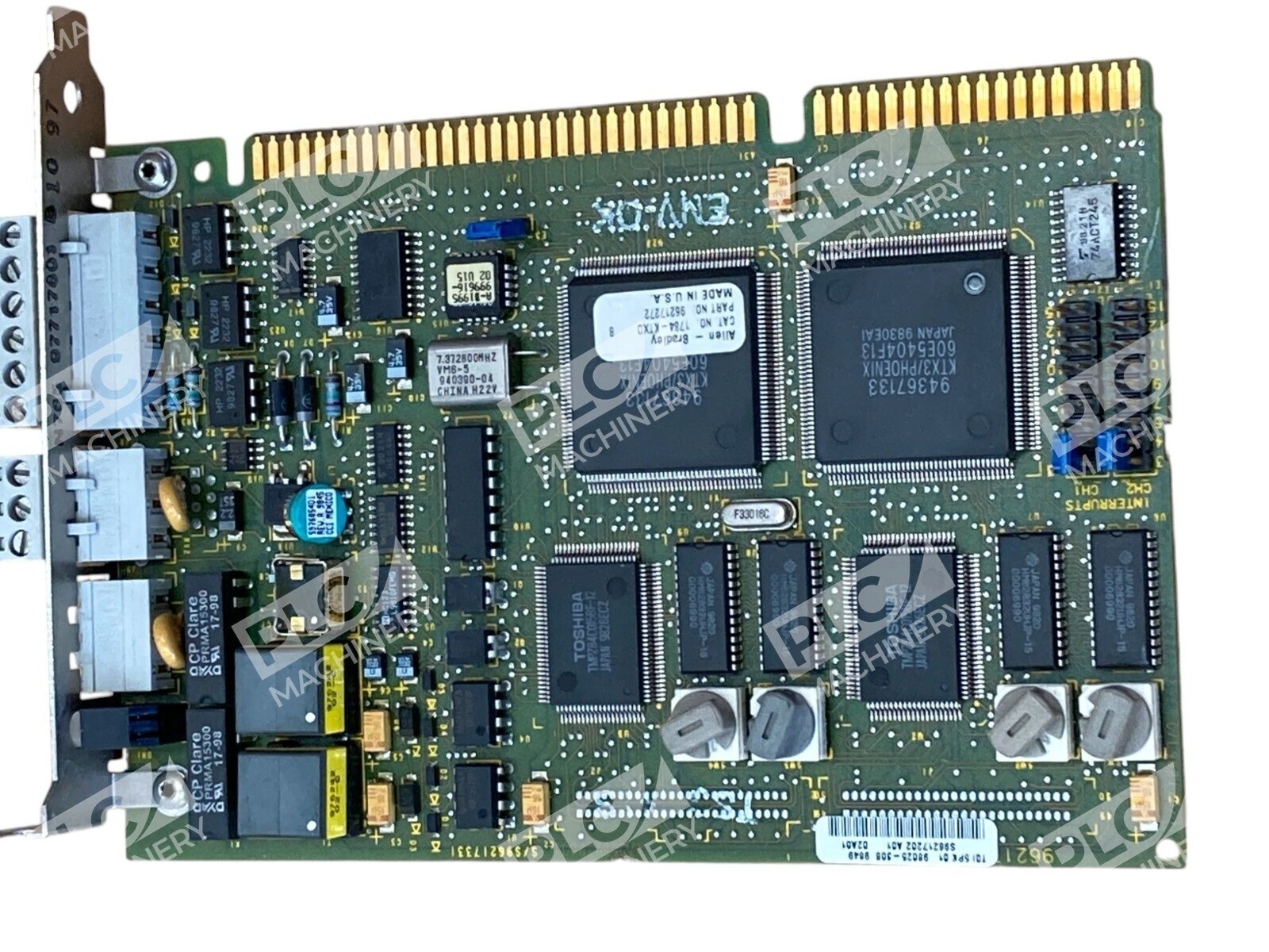
The Allen-Bradley 1784-KTX communication interface card is a proven legacy solution for integrating PLC-5 systems into Data Highway Plus (DH+) and DH-485 industrial networks. This half-sized ISA card has been the industry standard for connecting distributed control nodes, remote programming interfaces, and HMI systems to Allen-Bradley PLC-2, PLC-3, and PLC-5 controllers.
Key Features
- Single-channel 16-bit DH+ or DH-485 network interface
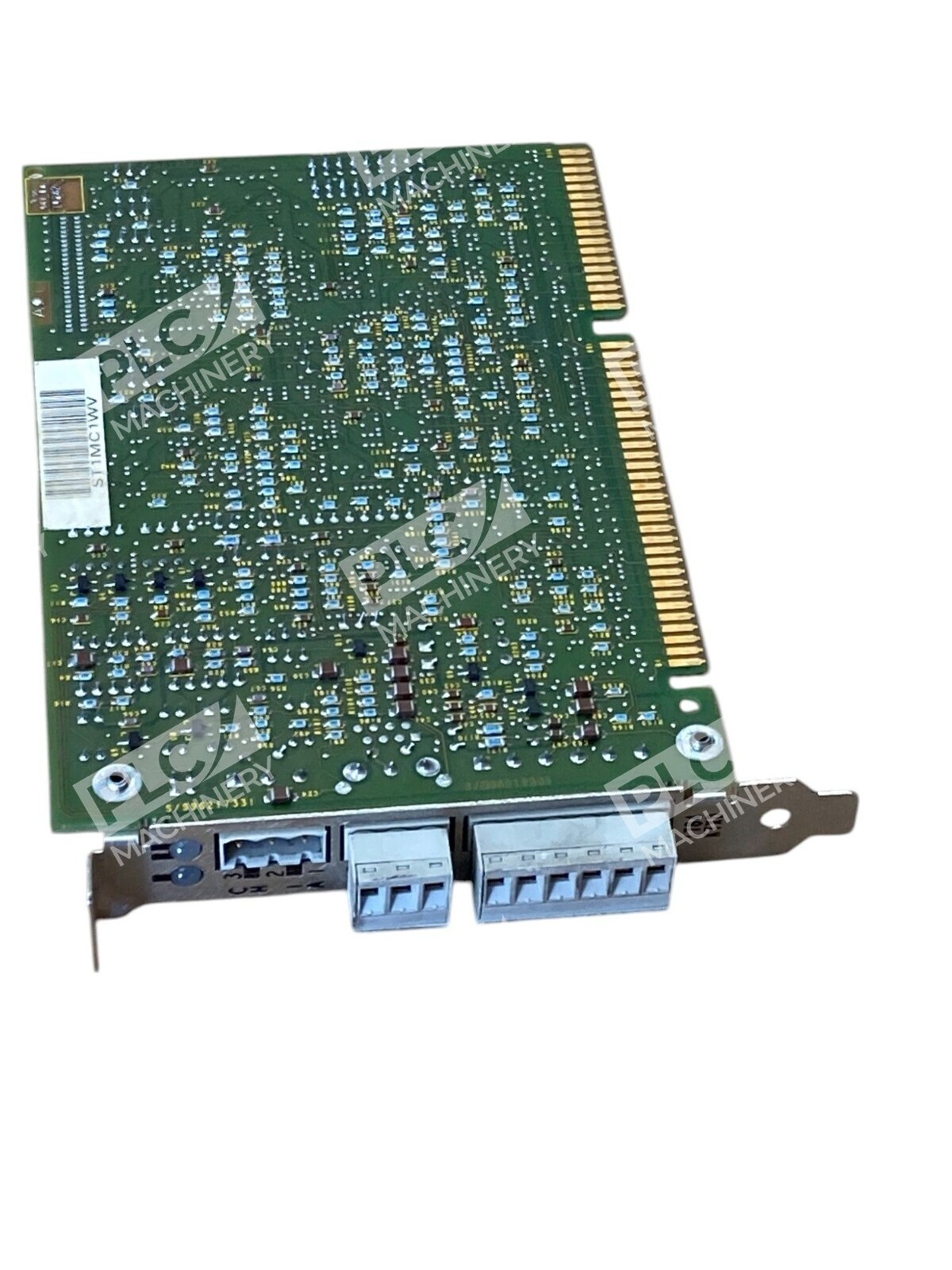
- Half-sized ISA card for 16-bit ISA/EISA slot installation
- Compatible with PLC-2, PLC-3, and PLC-5 direct-connect
- Supports remote programming, diagnostics, and data transfer
- CMOS technology with ESD protection requirements
- Configurable interrupt and base memory address settings
Technical Specifications
- Communication Protocol: DH+ and DH-485
- Network Channels: 1 (single active node)
- Interface Type: ISA half-sized card (16-bit ISA/EISA slot)
- Power Supply: 5V @ 1.75A, 12V @ 0.1A
- Operating Temperature: 0–60 °C (32–140 °F)
- Storage Temperature: -40–85 °C (-40–185 °F)
- Configuration: Switch-selectable interrupt and memory address
- Compatibility: Windows NT, RSLinx, RS-Logix 5
Typical Applications
The 1784-KTX is ideal for:
- Connecting personal computers to PLC-5 networks for remote programming and diagnostics
- Establishing communication between multiple PLC controllers on DH+ networks
- Integrating legacy automation systems with modern SCADA and HMI software
- Building distributed control architectures in manufacturing and process facilities
- Supporting network node expansion on existing industrial automation platforms
Compatibility & Replacements
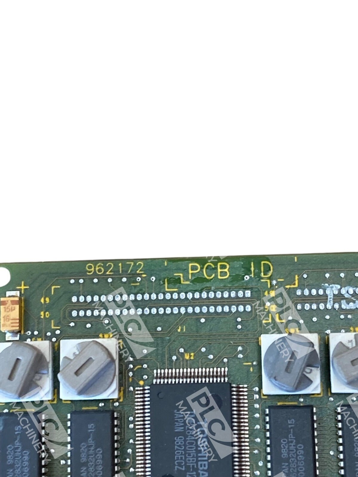
The 1784-KTX is designed for PLC-5 environments and works with RS-Logix 5, RSLinx, and Windows NT-based control systems. For modern ControlLogix systems, alternative cards such as the 1756-ENBT Ethernet interface or 1756-DHRIO DH+ remote I/O module provide updated connectivity options. Always verify your ISA slot type (16-bit required; 8-bit slots are incompatible) and configure interrupt/memory settings per the official Allen-Bradley user manual before installation. The PCB revision code A01 denotes the specific hardware configuration.